Guest post by Tom from Purpose Built Moto
Wiring your bike after customizing it can often be the most daunting part. If you’re a true DIY’er you won’t let anyone else do it either. So what are you to do? You’re going to have to learn a few things.
I recommend checking out this article on “Motorcycle electronic equipment” to get familiar with the electrical equipment on your bike before attempting to wire the bike.
I like to split this job in two, you have a running circuit and your accessories circuit, with 2 separate diagrams. This makes the drawings simpler and if anything goes wrong it’s easier to trace the problem.
(accessories shot)
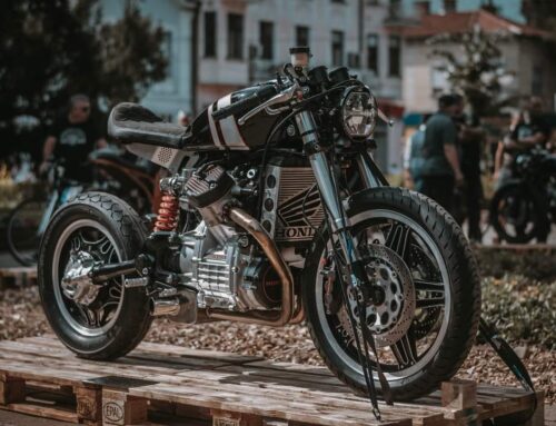
Before you think about wiring, mount everything on your bike from coils to your lights and speedo
Start by mounting your battery, and figuring out where your electrics tray will go. That should house your
- starter relay
- CDI
- Flasher unit or Black Box module
- Fuses or circuit breakers
Once that’s sorted I mount the Reg/Rec either underneath or next to the battery, it needs airflow as it gets pretty hot, DO NOT put it too close to other accessories or touching wires it may melt them. With a Café Racer or any Custom bike, most of the time the best place for all your electronics and connections is under the seat.
You’re ready to start wiring now . Some people prefer to use 1 wire run the length of the bike and tap off that for your positive, in my mind this way tends to lead to a lot of joins and if that 1 wire has an issue your bike is going to have big problems.
I like to use a Terminal strip and join all the positive wires in the electrics tray. I separate the terminals into sections
- Switching
- Lights
- Charging circuit
(diagram pic)
I also always draw my wiring diagram, but I’m good with electrics so use my ones to save you some time! Get the PDF’s here
Before we get going, make sure you use quality connectors or solder joints and heat shrink your connections. Now let’s start with the charging/running circuit.
(wiring materials)
- Run a lead from your battery –ve (Black) to a clean bare metal part of the frame and bolt it on, this turns your whole frame into a ground. Also be sure to ground your engine/gearbox case at one point. Then run from the +ve (Red) to the starter coil. Connect the other side of your starter coil to the starter motor. This is done in heavy duty wire.
- Run a standard 15A cable (red) to the main fuse (20-30A) then to your key ignition. From the key ignition, there will be 2 other cables, one goes to your charging circuit and coils, the other to a fuse for the lighting and accessories circuit (10-15A) .
- Start finishing up your Running circuit, connect the 3 (normally yellow) wires from the stator to the reg/rec then connect the red to the battery +ve and the green to the –ve. Some bikes (Honda CB750s) will have extra cables to connect from the reg/rec to the coils. If not it will be included in the signal generator and CDI unit.
- Get your signal generator and CDI unit plugged in, then run your coil fire cables (blue/orange) and connect the coils to your spark plugs. Most of the time your CDI, Reg/Rec and signal generator will all have plugs pre-fitted for you to use, no soldering or connectors required.
With your charging circuit finished it’s not time to get your lighting, switches and accessories sorted out. This guide is written including standard switches and buttons and excludes the use of a kill switch which can be put inline with the charging circuit active to the coils.
- you’ll have to run a few wires from your electrics tray to the front, I use a Black “snake skin” to protect my wiring from damage, and it looks a lot better than your standard plastic wrap or electrical tape. you’ll need
- 1 positive linked to the headlight, brake switch, horn and starter
- 1 orange switch wire for your starter
- 1 blue switch wire from your flasher relay
- 1 green wire for rear left indicator
- 1 brown wire for rear right indicators
- 1 green wire for the neutral light
- 1 orange switch wire for the front brake switch
- 1 Black earth wire
(snake skin and wire shot)
- Try to use solder connections on wire joins and good quality joiners for connection to switches and lights. The Grounding connections being especially important.
- Connect the positive cable to your switches headlight , brake, horn and starter
- Connect the orange wire to the other side of the starter switch
- Connect the Blue switch wire to the common terminal of the turn signal switch.
- The green and brown will terminate to the left and right sides, along with your front indicator actives.
- You’ll have spare terminals left on the hi/lo beam and the horn switches, connect these straight to the accessories.
- Now hook up your signal lights if you have them in the speedo cluster or triple clamp.(yellow for turn signal, blue for Hi beam, green for neutral)
- All of your accessories will need to have the black wires grounded, you can do this to the frame at any point or join them all and run a wire back to the electrics tray.
- Now work from the back of the bike back toward the electrics tray use snake skin here again. You’ll need.
- 1 red active wire for the rear brake switch, the running light, and the number plate light.
- 1 orange switch wire from the brake switch
- 1 green wire for rear left indicator
- 1 brown wire for rear right indicator
- 1 black earth wire
- Connecting at the electrics tray is a crucial step, this is where the wiring diagram comes in handy to make sure you get all your connections right.
- Connect your red active to the brake switch and the orange to the other side, then run it to your brake light also.
- Connect the rest of your lights and finish off by grounding the neutrals (black)
- The final step is to use your terminal strip to connect it all together and wire in the flasher relay. You should end up with something like this.
(electrics tray pic)
The final check if you have the tools is to check all your connections for a short to earth. This is as simple as going through all the positive wires and checking them with a multimeter to make sure there is no direct connection to the frame or another ground.
Now fire it up! I know there are simpler ways to wire a bike however in my experience a little extra work here can save you heartache if there is ever a problem. Simple fault finding is what I aim for.
If all of this seems a little complicated you can try a simple lighting control unit, the Purpose Built Moto Black box eliminates a lot of the complicated steps shown above to simplify your switches and wiring.
I hope you’ve taken some good info away from this that will help in wiring your café racer, again click here to download the PDF wiring Diagrams I use for your own custom café racer or chopper project. And also take a look at these specific diagrams: cafe racer wiring.
Thanks for taking the time.
About Tom:
Hi, I’m Tom an Australian motorcycle parts designer and custom builder. Running a small workshop under the name Purpose Built Moto I specialize in Small electronics components, LED lighting, Switches and control relays. I build client commissioned bikes and also have an online store where all my parts are available for purchase with worldwide shipping. Purpose Built Moto also hosts its own blog with a range of detailed step by step guides on hand making components on your own project.