motogadget m-unit wiring

Motorcycle wiring can be a real pain in the ass, especially when you’re not familiar with wiring and electronics (just like me!). If you want to simplify the wiring of your bike (and your life!) then MotoGadget has a great solution: the MotoGadget M-Unit. This intelligent device functions as a new heart of your motorcycle wiring harness and works both for noobs (just like me) and for the pro’s and everybody in between. In this article I’ll give you some handouts for the MotoGadget M-Unit wiring.

If you don’t want to invest in the MotoGadget M-Unit and you just want an “as simple as possible” wiring harness for your motorcycle, then check out my other article: Café Racer Wiring.

MotoGadget M-Unit Overview

MotoGadget is a German company that focusses on motorcycle electronics. And like the most of the products “Made in Germany”, quality is one of the most important USP’s. The company has a track record for many years of developing high-quality products for motorcycles and their cornerstone is the MotoGadget M-Unit. The latest M-Unit is the V2 and works like a control box for switching all necessary components and has a complete fuse box integrated. The box itself has the size of a pack of cigarettes and is resistant to water, weather and vibrations. All switching operations are digitally controlled, without mechanical relays, which makes it completely “solid state”. The system works for both 6V and 12V system and all connections can be made with terminal blocks. In short the MotoGadget M-Unit will simplify and upgrade your motorcycle electronics. Next to controlling switches, the M-Unit has an integrated alarm signal and can work with cool gadgets (it is a gadget after all) like RFID tags for starting/unlocking the bike. I’m not going to sum up all features and advantages of the M-Unit, so if you want to learn more, check it out here.

Wiring the MotoGadget M-Unit

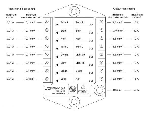
So, enough with the fluffy talk, let’s give you some handouts to get your M-Unit up and running! First it’s important to get familiar with the control unit itself. Here’s an overview of all inputs and outputs:MotoGadget M-Unit Overview

You don’t have to keep this overview with you all the time, since all text is actually on the M-Unit itself. The status of each circuit is shown by small red LED’s:

LED off input not active, output not powered
LED on input active, output powered – normal condition
Short flashing output shutdown due short-circuit or overload
Short flash each 2s alarm system active

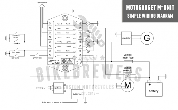
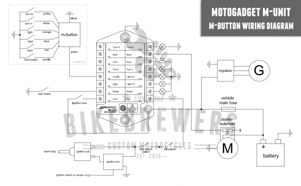
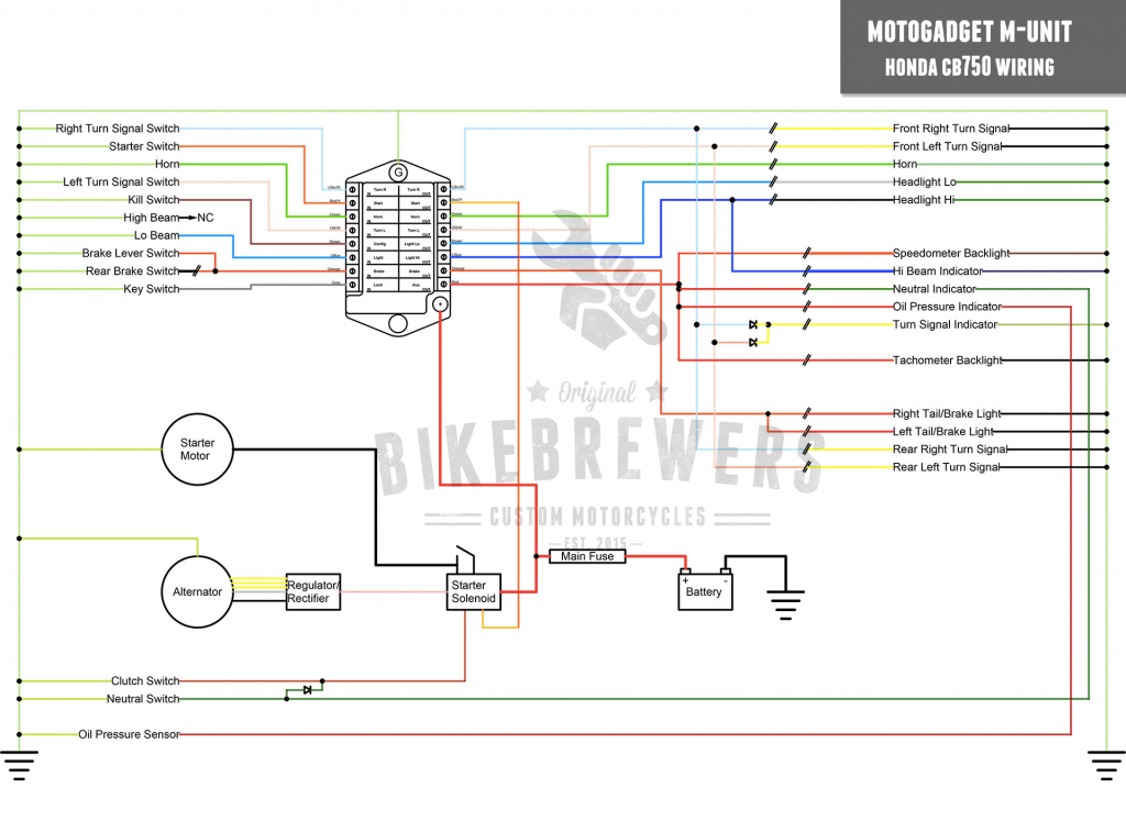
Below I’ve listed some standardized MotoGadget M-Unit wiring diagrams. There is a simple version and a version with the M-Button (a cool and original MotoGadget accessory that you place on your handlebar):

motogadget m-unit wiring diagram

motogadget m-button wiring diagram


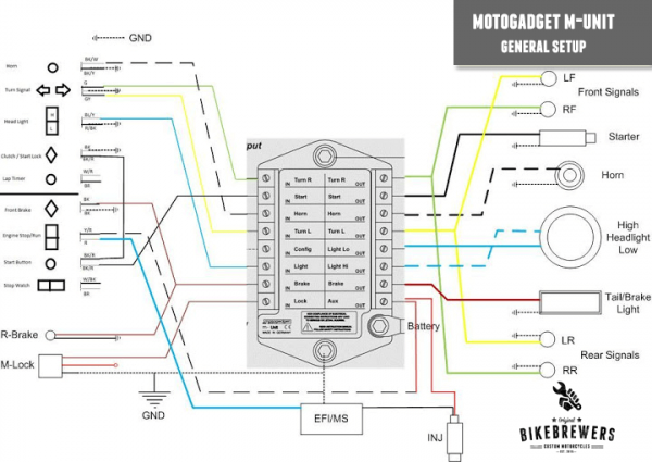
MotoGadget Wiring - General Setup

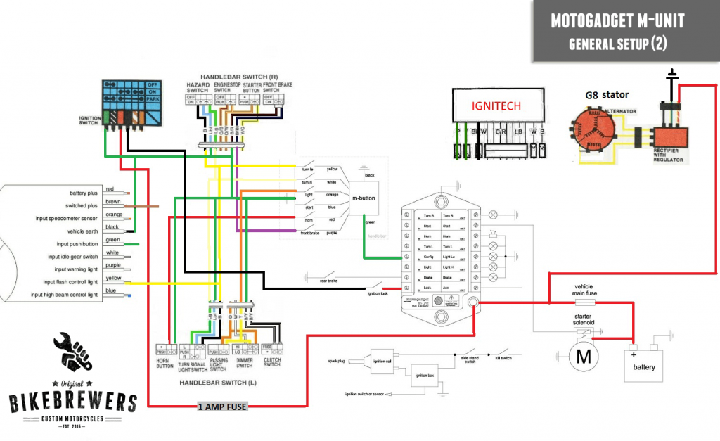
MotoGadget Wiring - General Setup (2) MotoGadget Wiring - Honda CB750

By Published On: January 2, 2017Categories: Articles50 Comments on MotoGadget M-Unit Wiring2.6 min readViews: 2574

Share This Story, Choose Your Platform!

About the Author: Ron Betist

Ron Betist grew up with motorcycles with a father heading the Amsterdam motorcycle police force. He has been riding (legally) for over 40 years and motorcycles are his true passion. With a life-long career in marketing and sales he has a huge international network. He joined as a contributor at BikeBrewers in 2017 to spread his word about bikes with the rest of the world.

50 Comments

  1. Matt McLeod (@KrankEng) January 2, 2017 at 7:31 pm - Reply

    Awesome Joeri! These diagrams will be very helpful when I use an M-unit on one of my project bikes! Thanks!

  2. Chris March 3, 2017 at 11:54 pm - Reply

    Brilliant post Joeri and very helpful, im still having some issues.I have removed all original wiring loom and installed the M-Unit, M-Lock, M-Button and M-Switch mini.
    As soon as I touch the “Start Out” blue cable to my starter solenoid (point 50) the bike immediately tries to start.

    I have tried this with the m-unit off and on with the same result (the bike tries to start).

    I removed the config wire to test and the same result.

    The M-Unit is acting like it has “always on” for the “Start Out”.

  3. Jason March 24, 2017 at 2:04 pm - Reply

    Very helpful, just 1 question though?

    Can you still use the conventional OEM switches that came with the bike or do you have to buy new handlebar switches?

    • Joeri March 24, 2017 at 2:07 pm - Reply

      Hi Jason,

      You can use all OEM switches with the M-unit! (and other stock items!)

  4. dave March 26, 2017 at 9:56 am - Reply

    hi i cant find a wiring diagram for a 4 button m-button setup as in which 4 wires out of the m-button do i use (im not using a f/brake switch at the handle bars) if you can help thanks

    • Joeri March 26, 2017 at 1:01 pm - Reply

      Hi Dave,

      It depends on which wires you already used for the other controls. You can edit the desired in/output at the config-port.

  5. Davy April 21, 2017 at 4:57 pm - Reply

    I’m wiring a Harley 1340 evo using the m-unit, its the second one I’ve used, the first five years ago on a gixer 11, now I’ve seen and read that the m-unit does not require a starter relay as one is built in, any help on the starter circuit would be a great help, I’ve everything else wired and working great, just haven’t touched the starter output circuit yet, I’ve trawled the web looking for help, but can’t find any ,,,thanks,,,

    • Joeri April 22, 2017 at 7:08 am - Reply

      Hi Davy,

      I’ll digg in to that and update the post if I can!

      • shaun miller April 3, 2018 at 12:46 pm - Reply

        I am stuck on the same thing, got power to my igntion module etc, but cant fire it up throught my stop/start.. any info would be appreciated.. do i need to run a seperate relay for the starter from the start switch

    • shaun miller January 17, 2018 at 1:10 pm - Reply

      I am using on myself on my 2005 sportster tracker… any help with wiring the m-unit to the twin tec ignition module would be a great help.

      cheers Shaun

  6. Davy April 22, 2017 at 11:35 am - Reply

    Much appreciated, I’m sort of stuck here, I do know the v2 model has a built in starter relay, but not sure if its a case of running the heavy duty positive from the battery terminal to the starter motor, and a switching wire from the v2 m-unit to the starter solenoid on the evo staryer, without additional relays or solenoid attached,

    • James August 1, 2017 at 4:34 pm - Reply

      You still have to have a solenoid to activate the starter. The m unit will use a built in relay to activate the solenoid to activate the starter. Your Harley may have a solenoid built in to the starter, in which case you will have to connect it directly to the m unit. I recommend watching the show to wire your motorcycle video that Revival Cycles put out, near the end Stephen goes over a few different starter circuits. Hope this helps!

  7. Andrew April 29, 2017 at 4:27 pm - Reply

    Just picked up an m-unit v.2 for a complete wiring overhaul from scratch. Pretty straight forward on wiring the switches for horn, lights, signals, etc. But I’m struggling with how to get my stock speedometer cluster with all its indicator lights connected properly. Can someone help??

    • Joeri April 30, 2017 at 10:46 am - Reply

      Hi Andrew,

      There are different setups possible. Neutral light can be added from START OUT on the same way as the clutch or side stand switch. Oil pressure can be added with AUX. If I have some time I’ll try to add another diagram later.

      And of course you can use the Motogadget Breakout Box A/B in combination with a Motoscope.

  8. Andrew April 30, 2017 at 3:47 pm - Reply

    Thanks – yeah if you have the time and inclination to post a diagram of would be much appreciated. It’s a 2008 Honda Shadow VT750C2 for what it’s worth, but I’ve chopped it up so it’s not really stock anymore. I guess I’m just a little unclear about what to do with all of the additional items other than lights and the starter. If I literally pull all the stock wiring, fuses and relays off of the bike and do a ground-up wiring job w the m-unit, I’ve got clutch switch, fan, sidestand switch, and all the speedometer indicator lights, which are oil pressure, high beam indicator, neutral indicator, and temperature indicator. I realize not all of these items are really “required” so to speak, but I’d like to at least maintain fan functionality, and both oil pressure and temperature indicator lights. I’m trying to retain the stock speedometer and housing too, at least for now. Can’t sink any more major cash into this thing at the moment without some marital headaches. Thanks to you and any other responders for any help you can give me. It’s greatly appreciated!

  9. Eric May 21, 2017 at 1:16 pm - Reply

    I just bought a bike that has this installed. 1977 gs750-kickstart only. I started it and rode it 5 -9 times the first day. Went to start it again and nothing- It isnt receaving power to the coils- cant even push start it- The “LOCK” light is lit up. Is this supposed to be lit up? I charged the battery and nothing LOST!?

  10. Casey Albert June 8, 2017 at 4:51 pm - Reply

    Eric;
    I have just purchased a MotoGadget for use on my ’79 GS1000s to replace the fuses, ignition key, blinker relays, etc.. I am still in the “learning” process.

    Take a look at this video and see if this helps. It is possible you simply don’t have a good “ground.”

    Good Luck!

    Casey

  11. Casey Albert June 9, 2017 at 8:59 pm - Reply

    Anytime!
    Also, you can get the manual for your unit on the MotoGadget site.
    I’m still in the “research” phase regarding just what I need to do to convert my old system to this newfangled one, but I think it will bring my old bike into the digital age.

    Casey

  12. Bastien June 11, 2017 at 8:31 pm - Reply

    Hi,

    thanks for posting that diagrams.
    I’m wiring a M-unit on a 81 Yamha xv750, I just have one doubt remaining about the regulator/rectifier, I am ok with the wire from the RR to the batterie, but on my bike, I also have a brown wire supplying power to the turn signals, the horn, the speedo and the RR. I don’t have any idea what is the purpose of this cable to the rectifier. Do I need to connect that brown wire from the Aux output to the rectifier ?

    Thanks in advance for you help

    Bastien

    • James August 1, 2017 at 4:38 pm - Reply

      Yes connect the brown wire to your aux output, I struggled with that for a week. I have an 80 kz750 so they are very similar.

  13. james June 13, 2017 at 11:52 am - Reply

    I bought an M-Unit and M-button to replace the tired old wiring harness on my xt500 and it’s a ball ache!! I’ve got a 12v electronic ignition set up and don’t see much info anywhere on integrating the CDI system. Added to that, the XT’s lighting coil supplies AC power to the lights. No response from the tech support at Motogadget unfortunately. I’m sure this is a good product but the installation is nowhere near as straight forward as I imagined especially with my limited electrical knowledge. Think I’ll go back to a loom.

    • Joeri June 13, 2017 at 12:49 pm - Reply

      Hi James,

      For CDI-systems Motogadget offers a special signal sensor. Weird that you don’t get any response from them. Have you tried to call them already?

      Joeri

    • Rob October 1, 2017 at 7:52 pm - Reply

      I had similar problems on my cb400t. I got mine from Revival Cycle and they answer pretty regularly. They instructed me to put the b/w kill wire from the cdi into the Aux or ignition input depending on which m.unit version you have through a normally closed relay. It has to be normally closed so that way when the m.unit input for Aux or ignition is used the contact will open powering the control coil, and when closed it grounds the b/w kill cdi wire.

  14. Peter September 14, 2017 at 7:27 pm - Reply

    Wondering why there needs to be a relay with the munit ? I thought that the munit has its own relays ?

  15. Gabor September 27, 2017 at 12:18 am - Reply

    Peter,
    On mine, an 88 fzr, I had to keep the fuel pump relay as well as the starter solenoid (relay).
    I bought a fused starter solenoid and ran the power to the m-unit through there. This allowed me to get rid of the main fuse.

    • Gabor September 27, 2017 at 12:19 am - Reply

      The m-unit only has the flasher relay and fuses built in..

  16. Mike LaRocque November 16, 2017 at 8:55 pm - Reply

    Im looking to clean up all the wiring on my 2016 Indian Scout. The stock wiring is just ridiculous and also a canbus system. I’ve been scouring the web and cant tell if this will even work with my bike. Is there anyone I can email or call to discuss this?

  17. Matjaž Prosen November 28, 2017 at 6:21 pm - Reply

    Hi, Do jou have BMW K100 diagram

  18. RJ Sha December 26, 2017 at 5:01 am - Reply

    Hi Joeri,

    This is a great article and tons of information for a newbie like me. Quick question – is the wiring diagram above for the honda cb750 dohc or sohc? I am planning on cleaning up the wiring for my 750 dohc. If it is for a sohc, would you or anyone on this have m unit diagram for the dohc?

    Thanks
    RJ

  19. Casey Albert February 4, 2018 at 8:43 pm - Reply

    M-Unit Blue, Lessons learned….(My bike is a 1979 Suzuki GS1000S) I’m writing in my effort to assist, and learn from people regarding the installation of the M-Units. Most things are fairly similar to both models(I think). In reading the above posts, I thought I would add; The other day, I hooked up my battery and noticed ALL of the lights flashing brightly. I just found out that the M-Units don’t like that! Make your battery connections first, then connect the M-Unit. It’s in the book, but I missed that earlier.
    I am using an AUX output to power console lights. I’m going to go back and look at my wiring diagrams, but I’m not sure if polarity on lights really matters. I plan to make sure I do it correctly when I get home. So, I used one wire to the lights, and the other wire to ground.
    I found out my “kill” switch works in reverse, OFF is ON….. Learned this from Stephan on the Revival Cycles videos. Very informative!!
    You need your wiring diagram. I took mine to a print shop and printed it out about 3 feet by 5 feet. Made a lot more sense. And, found out that wiring diagrams from manuals may not be correct. I took apart my left handle switch as it is responsible for most of my inputs, and found misrepresented wiring. Ground and power for two switches were in error in the diagrams.
    I was able to get rid of all of the large connectors and moved all my “front end” wires to the headlamp housing. I used “ethernet” stranded wires for my “input” wires.
    I roughed out my wiring using “hardware store” hardware, just to see if it would function. I checked function before hooking up “output” wires(look at output lights).
    I am working on Phase three to make my wiring harness “aircraft quality” and professional.
    I found that because these gadgets are earth-input…….output(power) to device, it took me a bit to get it straight. I think I have it straight…
    I hope some of this will help someone.

    • justin May 8, 2019 at 6:05 am - Reply

      thanks. ive been wondering why all the lights keep coming on as soon as I ground the m-unit.

  20. Steven Iglesias May 8, 2018 at 1:28 pm - Reply

    Hi I need some help with wiring an M Button to Harley OEM switches.

    What I got is:

    M Button Harley Switch
    L Signal Yellow White/Violet
    R Signal White White/Brown
    HL power Orange? Blue (Light Breaker)
    High ? White
    Low ? Yellow
    brake Purple red yellow
    b power ? orange/white (Acc Breaker)
    Horn Red Yellow/Black
    H power ? Orange /White (Acc Breaker)

    Turn Signal, Horn, and break switches tie into Accessories breaker. Blue wire tie into Light Breaker on Harley schematic.

    Question is what do I do with these extra wires? Do I ground them? Run the wires directly into the input of the M unit with the Output going to the device? Or do I splice them together with the corresponding output wire to the M button and the Green wire does all the work? Any advice would be appreciated thanks!

  21. Bastien June 19, 2018 at 7:18 am - Reply

    Hi, Hi I need some help with wiring an M-unit blue honda CX 400 with CDI
    I do not know or connect the M-Unit Blue “ignition” terminal to the CDI.
    I saw that you had a Mi-Unit V2 circuit diagram on honda cx. Maybe could you again for the M-Unit blue.
    I thank you in advance.

  22. Matt June 25, 2018 at 8:50 pm - Reply

    I’m installing an M-unit blue on a 2000 HD Dyna Wide Glide. The diagrams and instructions I’ve seen so far indicate that the M-unit replaces the fuse box, turn signal module and start relay. What I haven’t seen mention of are the ignition module and its 16 wires connected to the following (also not mentioned in any install instructions):
    – manifold air pressure sensor
    – crank position sensor
    – cam position sensor
    – bank angle sensor
    – data link

    Of course, the ignition module ALSO connects to the speedometer and ignition coil, so getting rid of the ignition module doesn’t seem like an option. Or, is it? I’ve read stories about how the M-unit simplifies and reduces the wiring – one user claiming he “filled a bucket” with the wires he removed. So far, my bucket is still empty. The fuse box, turn signal module and start relay are gone, but their wires still remain.

    So tell me: Is the ignition module still needed (seems it would be – doesn’t it control the ignition timing?), or is it the bucket-filling ectomy? What about the sensors connected to it? And if they can all be pulled, what about the leads to the speedo and coil?

  23. Stewart Kinsey July 31, 2018 at 12:49 pm - Reply

    Wiring a m unit blue on my Suzuki bandit. From the alternator/generator I have the positive but also another wire.. Where does it go?

    • Igorov September 13, 2018 at 7:14 pm - Reply

      Usually you have 3 yellow cables and a red one that goes from the stator till the rectifier.
      (usually you can cut them and make them longer, the sequence is not relevant, you can cross cable between the yellow cables no problem. )
      Focus on the red and black cable out of the rectifier, the black cable you connect to the frame ( – ), the red cable you connect to the red cable that gets to the battery but dont forget to connect it to the fuse and not straight to the battery.

      Thats all ;)

  24. Jason Weiss August 11, 2018 at 1:15 am - Reply

    I just cam across this article, and I’m intrigued by the possibilities the M.Unit holds. Will this technology work on a 1966 Triumph Bonneville t120r kickstart? The bike is a true bobber with only a headlight and brake light. I’d like to add turn signals and a speedo. It has a Podtronics Regulator / Rectifier and Pazon Electronic Ignition. Please let me know if the m.unit would be compatible, and if you have a wiring chart for it.

    Thank you,
    Jason

  25. Igorov September 13, 2018 at 7:21 pm - Reply

    Yep it will work just fine, if you have a bobber you can add the M-button, you hide it inside the bar and you connect all the push buttons by passing the cables inside the bar.
    You will get a clean minimal install and no need to pass the cables from the push buttons to the m-unit and then back to the Lights and turn signals etc.

    You can actually do as I did, delete all speedos and key locker. I use my cellphone as key ;)

    Its a really cool piece of tech

  26. Rogier February 24, 2019 at 5:09 pm - Reply

    I’m wiring a Honda GL1200 cafe with a brand new M-unit basic. Almost ready. No power connected yet, but noticed that power connection of M-unit and ground connection hardly gives any resistance or ohms on my multi-meter. Even when disconnected from the entire wiring system (but still bolted to the base plate). I’m now hesitating to put power to the system as a do not know whether this is normal and things are settling in when power is connected. Just checking to be sure. Anyone? Thanks in advance..

  27. derdizzy March 10, 2019 at 12:33 pm - Reply

    Hello,
    is it possible, that the diode in your CB750 wiring diagram is facing into the wrong direction?
    I think this way the diode doesn’t make sense or am I wrong?

  28. Brock Prince March 29, 2019 at 7:44 pm - Reply

    I am re-wiring a 1977 CB 550 F. I have factory hand switches. But cannot get the blinkers or the high beams to respond. Can anyone help me. I can get the bike to start and had lights to come on but that’s it

  29. jacopo May 27, 2019 at 4:24 pm - Reply

    hey guys!
    do you have a wiring scheme for R65 Bmw + mUnit !! something really easy!!

  30. Stu Sanders October 7, 2019 at 12:28 am - Reply

    I think there is a mistake in the simplified m gadget wiring diagram , you show the side stand and kill switch in parallel, I think they should be in series to work as intended.
    If not my apologies. But please explain why .

  31. Stu Sanders October 7, 2019 at 12:37 am - Reply

    The Neutral switch would have to be tied into the side-stand . So the side stand would have to be up when it is shifted out of neutral to take over the ground , if you wanted it to run the motor while the side stand is down

  32. Tom October 24, 2019 at 2:50 am - Reply

    Hi do you have the wiring diagram for k75c 1986 ! I want To change All the wiring and put m unit Thanks

  33. Steve Lindsay June 27, 2020 at 7:57 pm - Reply

    I have a dozen or so Japanese bikes from the 1980s, many have wiring issues. A number of bikes will never be roadworthy again, but the engines are perfect for other projects. I built Hot Rods, Bobber Style Bikes for years, I’m semi-retired now and want to build some all-terrain Karts and buggies with some of the leftover bikes but don’t want to go through the pains of wiring them into other vehicles using the original wiring for numerous reasons. I want lights signal, all the regular roadworthy stuff without the hassle of using the wiring harness from the bikes many of which have shorts and botched wring. The M unit is new to me. Does it take the place of a regulator rectifier?. What electrical do I need to keep from the bikes to put them in something else using the M unit? Thank You for any guidance you can provide in a summary or reply.

  34. Richard August 24, 2022 at 6:01 pm - Reply

    Hoi zijn er voor de honda cb500 1995 misschien ook een diagram voor de m. Blue zo dat ik hem op een goede manier kan instaleren als er iemand is die dat heeft of mij daar bij kan helpen mag je me mailen smid_richard@hotmail.com alle hulp is zeer welkom. Ik heb zowel de hendelbar switchen en de m Button en de blue m brain. Al vast bedankt gr Richard

Leave A Comment

For security, use of Google's reCAPTCHA service is required which is subject to the Google Privacy Policy and Terms of Use.

Tags

motogadget m-unit wiring

Motorcycle wiring can be a real pain in the ass, especially when you’re not familiar with wiring and electronics (just like me!). If you want to simplify the wiring of your bike (and your life!) then MotoGadget has a great solution: the MotoGadget M-Unit. This intelligent device functions as a new heart of your motorcycle wiring harness and works both for noobs (just like me) and for the pro’s and everybody in between. In this article I’ll give you some handouts for the MotoGadget M-Unit wiring.

If you don’t want to invest in the MotoGadget M-Unit and you just want an “as simple as possible” wiring harness for your motorcycle, then check out my other article: Café Racer Wiring.

MotoGadget M-Unit Overview

MotoGadget is a German company that focusses on motorcycle electronics. And like the most of the products “Made in Germany”, quality is one of the most important USP’s. The company has a track record for many years of developing high-quality products for motorcycles and their cornerstone is the MotoGadget M-Unit. The latest M-Unit is the V2 and works like a control box for switching all necessary components and has a complete fuse box integrated. The box itself has the size of a pack of cigarettes and is resistant to water, weather and vibrations. All switching operations are digitally controlled, without mechanical relays, which makes it completely “solid state”. The system works for both 6V and 12V system and all connections can be made with terminal blocks. In short the MotoGadget M-Unit will simplify and upgrade your motorcycle electronics. Next to controlling switches, the M-Unit has an integrated alarm signal and can work with cool gadgets (it is a gadget after all) like RFID tags for starting/unlocking the bike. I’m not going to sum up all features and advantages of the M-Unit, so if you want to learn more, check it out here.

Wiring the MotoGadget M-Unit

So, enough with the fluffy talk, let’s give you some handouts to get your M-Unit up and running! First it’s important to get familiar with the control unit itself. Here’s an overview of all inputs and outputs:MotoGadget M-Unit Overview

You don’t have to keep this overview with you all the time, since all text is actually on the M-Unit itself. The status of each circuit is shown by small red LED’s:

LED off input not active, output not powered
LED on input active, output powered – normal condition
Short flashing output shutdown due short-circuit or overload
Short flash each 2s alarm system active

Below I’ve listed some standardized MotoGadget M-Unit wiring diagrams. There is a simple version and a version with the M-Button (a cool and original MotoGadget accessory that you place on your handlebar):
motogadget m-unit wiring diagram

motogadget m-button wiring diagram


MotoGadget Wiring - General Setup

MotoGadget Wiring - General Setup (2) MotoGadget Wiring - Honda CB750

By Published On: January 2, 2017Categories: Articles50 Comments on MotoGadget M-Unit Wiring2.6 min readViews: 2574

Share This Story, Choose Your Platform!

About the Author: Ron Betist

Ron Betist grew up with motorcycles with a father heading the Amsterdam motorcycle police force. He has been riding (legally) for over 40 years and motorcycles are his true passion. With a life-long career in marketing and sales he has a huge international network. He joined as a contributor at BikeBrewers in 2017 to spread his word about bikes with the rest of the world.

50 Comments

  1. Matt McLeod (@KrankEng) January 2, 2017 at 7:31 pm - Reply

    Awesome Joeri! These diagrams will be very helpful when I use an M-unit on one of my project bikes! Thanks!

  2. Chris March 3, 2017 at 11:54 pm - Reply

    Brilliant post Joeri and very helpful, im still having some issues.I have removed all original wiring loom and installed the M-Unit, M-Lock, M-Button and M-Switch mini.
    As soon as I touch the “Start Out” blue cable to my starter solenoid (point 50) the bike immediately tries to start.

    I have tried this with the m-unit off and on with the same result (the bike tries to start).

    I removed the config wire to test and the same result.

    The M-Unit is acting like it has “always on” for the “Start Out”.

  3. Jason March 24, 2017 at 2:04 pm - Reply

    Very helpful, just 1 question though?

    Can you still use the conventional OEM switches that came with the bike or do you have to buy new handlebar switches?

    • Joeri March 24, 2017 at 2:07 pm - Reply

      Hi Jason,

      You can use all OEM switches with the M-unit! (and other stock items!)

  4. dave March 26, 2017 at 9:56 am - Reply

    hi i cant find a wiring diagram for a 4 button m-button setup as in which 4 wires out of the m-button do i use (im not using a f/brake switch at the handle bars) if you can help thanks

    • Joeri March 26, 2017 at 1:01 pm - Reply

      Hi Dave,

      It depends on which wires you already used for the other controls. You can edit the desired in/output at the config-port.

  5. Davy April 21, 2017 at 4:57 pm - Reply

    I’m wiring a Harley 1340 evo using the m-unit, its the second one I’ve used, the first five years ago on a gixer 11, now I’ve seen and read that the m-unit does not require a starter relay as one is built in, any help on the starter circuit would be a great help, I’ve everything else wired and working great, just haven’t touched the starter output circuit yet, I’ve trawled the web looking for help, but can’t find any ,,,thanks,,,

    • Joeri April 22, 2017 at 7:08 am - Reply

      Hi Davy,

      I’ll digg in to that and update the post if I can!

      • shaun miller April 3, 2018 at 12:46 pm - Reply

        I am stuck on the same thing, got power to my igntion module etc, but cant fire it up throught my stop/start.. any info would be appreciated.. do i need to run a seperate relay for the starter from the start switch

    • shaun miller January 17, 2018 at 1:10 pm - Reply

      I am using on myself on my 2005 sportster tracker… any help with wiring the m-unit to the twin tec ignition module would be a great help.

      cheers Shaun

  6. Davy April 22, 2017 at 11:35 am - Reply

    Much appreciated, I’m sort of stuck here, I do know the v2 model has a built in starter relay, but not sure if its a case of running the heavy duty positive from the battery terminal to the starter motor, and a switching wire from the v2 m-unit to the starter solenoid on the evo staryer, without additional relays or solenoid attached,

    • James August 1, 2017 at 4:34 pm - Reply

      You still have to have a solenoid to activate the starter. The m unit will use a built in relay to activate the solenoid to activate the starter. Your Harley may have a solenoid built in to the starter, in which case you will have to connect it directly to the m unit. I recommend watching the show to wire your motorcycle video that Revival Cycles put out, near the end Stephen goes over a few different starter circuits. Hope this helps!

  7. Andrew April 29, 2017 at 4:27 pm - Reply

    Just picked up an m-unit v.2 for a complete wiring overhaul from scratch. Pretty straight forward on wiring the switches for horn, lights, signals, etc. But I’m struggling with how to get my stock speedometer cluster with all its indicator lights connected properly. Can someone help??

    • Joeri April 30, 2017 at 10:46 am - Reply

      Hi Andrew,

      There are different setups possible. Neutral light can be added from START OUT on the same way as the clutch or side stand switch. Oil pressure can be added with AUX. If I have some time I’ll try to add another diagram later.

      And of course you can use the Motogadget Breakout Box A/B in combination with a Motoscope.

  8. Andrew April 30, 2017 at 3:47 pm - Reply

    Thanks – yeah if you have the time and inclination to post a diagram of would be much appreciated. It’s a 2008 Honda Shadow VT750C2 for what it’s worth, but I’ve chopped it up so it’s not really stock anymore. I guess I’m just a little unclear about what to do with all of the additional items other than lights and the starter. If I literally pull all the stock wiring, fuses and relays off of the bike and do a ground-up wiring job w the m-unit, I’ve got clutch switch, fan, sidestand switch, and all the speedometer indicator lights, which are oil pressure, high beam indicator, neutral indicator, and temperature indicator. I realize not all of these items are really “required” so to speak, but I’d like to at least maintain fan functionality, and both oil pressure and temperature indicator lights. I’m trying to retain the stock speedometer and housing too, at least for now. Can’t sink any more major cash into this thing at the moment without some marital headaches. Thanks to you and any other responders for any help you can give me. It’s greatly appreciated!

  9. Eric May 21, 2017 at 1:16 pm - Reply

    I just bought a bike that has this installed. 1977 gs750-kickstart only. I started it and rode it 5 -9 times the first day. Went to start it again and nothing- It isnt receaving power to the coils- cant even push start it- The “LOCK” light is lit up. Is this supposed to be lit up? I charged the battery and nothing LOST!?

  10. Casey Albert June 8, 2017 at 4:51 pm - Reply

    Eric;
    I have just purchased a MotoGadget for use on my ’79 GS1000s to replace the fuses, ignition key, blinker relays, etc.. I am still in the “learning” process.

    Take a look at this video and see if this helps. It is possible you simply don’t have a good “ground.”

    Good Luck!

    Casey

  11. Casey Albert June 9, 2017 at 8:59 pm - Reply

    Anytime!
    Also, you can get the manual for your unit on the MotoGadget site.
    I’m still in the “research” phase regarding just what I need to do to convert my old system to this newfangled one, but I think it will bring my old bike into the digital age.

    Casey

  12. Bastien June 11, 2017 at 8:31 pm - Reply

    Hi,

    thanks for posting that diagrams.
    I’m wiring a M-unit on a 81 Yamha xv750, I just have one doubt remaining about the regulator/rectifier, I am ok with the wire from the RR to the batterie, but on my bike, I also have a brown wire supplying power to the turn signals, the horn, the speedo and the RR. I don’t have any idea what is the purpose of this cable to the rectifier. Do I need to connect that brown wire from the Aux output to the rectifier ?

    Thanks in advance for you help

    Bastien

    • James August 1, 2017 at 4:38 pm - Reply

      Yes connect the brown wire to your aux output, I struggled with that for a week. I have an 80 kz750 so they are very similar.

  13. james June 13, 2017 at 11:52 am - Reply

    I bought an M-Unit and M-button to replace the tired old wiring harness on my xt500 and it’s a ball ache!! I’ve got a 12v electronic ignition set up and don’t see much info anywhere on integrating the CDI system. Added to that, the XT’s lighting coil supplies AC power to the lights. No response from the tech support at Motogadget unfortunately. I’m sure this is a good product but the installation is nowhere near as straight forward as I imagined especially with my limited electrical knowledge. Think I’ll go back to a loom.

    • Joeri June 13, 2017 at 12:49 pm - Reply

      Hi James,

      For CDI-systems Motogadget offers a special signal sensor. Weird that you don’t get any response from them. Have you tried to call them already?

      Joeri

    • Rob October 1, 2017 at 7:52 pm - Reply

      I had similar problems on my cb400t. I got mine from Revival Cycle and they answer pretty regularly. They instructed me to put the b/w kill wire from the cdi into the Aux or ignition input depending on which m.unit version you have through a normally closed relay. It has to be normally closed so that way when the m.unit input for Aux or ignition is used the contact will open powering the control coil, and when closed it grounds the b/w kill cdi wire.

  14. Peter September 14, 2017 at 7:27 pm - Reply

    Wondering why there needs to be a relay with the munit ? I thought that the munit has its own relays ?

  15. Gabor September 27, 2017 at 12:18 am - Reply

    Peter,
    On mine, an 88 fzr, I had to keep the fuel pump relay as well as the starter solenoid (relay).
    I bought a fused starter solenoid and ran the power to the m-unit through there. This allowed me to get rid of the main fuse.

    • Gabor September 27, 2017 at 12:19 am - Reply

      The m-unit only has the flasher relay and fuses built in..

  16. Mike LaRocque November 16, 2017 at 8:55 pm - Reply

    Im looking to clean up all the wiring on my 2016 Indian Scout. The stock wiring is just ridiculous and also a canbus system. I’ve been scouring the web and cant tell if this will even work with my bike. Is there anyone I can email or call to discuss this?

  17. Matjaž Prosen November 28, 2017 at 6:21 pm - Reply

    Hi, Do jou have BMW K100 diagram

  18. RJ Sha December 26, 2017 at 5:01 am - Reply

    Hi Joeri,

    This is a great article and tons of information for a newbie like me. Quick question – is the wiring diagram above for the honda cb750 dohc or sohc? I am planning on cleaning up the wiring for my 750 dohc. If it is for a sohc, would you or anyone on this have m unit diagram for the dohc?

    Thanks
    RJ

  19. Casey Albert February 4, 2018 at 8:43 pm - Reply

    M-Unit Blue, Lessons learned….(My bike is a 1979 Suzuki GS1000S) I’m writing in my effort to assist, and learn from people regarding the installation of the M-Units. Most things are fairly similar to both models(I think). In reading the above posts, I thought I would add; The other day, I hooked up my battery and noticed ALL of the lights flashing brightly. I just found out that the M-Units don’t like that! Make your battery connections first, then connect the M-Unit. It’s in the book, but I missed that earlier.
    I am using an AUX output to power console lights. I’m going to go back and look at my wiring diagrams, but I’m not sure if polarity on lights really matters. I plan to make sure I do it correctly when I get home. So, I used one wire to the lights, and the other wire to ground.
    I found out my “kill” switch works in reverse, OFF is ON….. Learned this from Stephan on the Revival Cycles videos. Very informative!!
    You need your wiring diagram. I took mine to a print shop and printed it out about 3 feet by 5 feet. Made a lot more sense. And, found out that wiring diagrams from manuals may not be correct. I took apart my left handle switch as it is responsible for most of my inputs, and found misrepresented wiring. Ground and power for two switches were in error in the diagrams.
    I was able to get rid of all of the large connectors and moved all my “front end” wires to the headlamp housing. I used “ethernet” stranded wires for my “input” wires.
    I roughed out my wiring using “hardware store” hardware, just to see if it would function. I checked function before hooking up “output” wires(look at output lights).
    I am working on Phase three to make my wiring harness “aircraft quality” and professional.
    I found that because these gadgets are earth-input…….output(power) to device, it took me a bit to get it straight. I think I have it straight…
    I hope some of this will help someone.

    • justin May 8, 2019 at 6:05 am - Reply

      thanks. ive been wondering why all the lights keep coming on as soon as I ground the m-unit.

  20. Steven Iglesias May 8, 2018 at 1:28 pm - Reply

    Hi I need some help with wiring an M Button to Harley OEM switches.

    What I got is:

    M Button Harley Switch
    L Signal Yellow White/Violet
    R Signal White White/Brown
    HL power Orange? Blue (Light Breaker)
    High ? White
    Low ? Yellow
    brake Purple red yellow
    b power ? orange/white (Acc Breaker)
    Horn Red Yellow/Black
    H power ? Orange /White (Acc Breaker)

    Turn Signal, Horn, and break switches tie into Accessories breaker. Blue wire tie into Light Breaker on Harley schematic.

    Question is what do I do with these extra wires? Do I ground them? Run the wires directly into the input of the M unit with the Output going to the device? Or do I splice them together with the corresponding output wire to the M button and the Green wire does all the work? Any advice would be appreciated thanks!

  21. Bastien June 19, 2018 at 7:18 am - Reply

    Hi, Hi I need some help with wiring an M-unit blue honda CX 400 with CDI
    I do not know or connect the M-Unit Blue “ignition” terminal to the CDI.
    I saw that you had a Mi-Unit V2 circuit diagram on honda cx. Maybe could you again for the M-Unit blue.
    I thank you in advance.

  22. Matt June 25, 2018 at 8:50 pm - Reply

    I’m installing an M-unit blue on a 2000 HD Dyna Wide Glide. The diagrams and instructions I’ve seen so far indicate that the M-unit replaces the fuse box, turn signal module and start relay. What I haven’t seen mention of are the ignition module and its 16 wires connected to the following (also not mentioned in any install instructions):
    – manifold air pressure sensor
    – crank position sensor
    – cam position sensor
    – bank angle sensor
    – data link

    Of course, the ignition module ALSO connects to the speedometer and ignition coil, so getting rid of the ignition module doesn’t seem like an option. Or, is it? I’ve read stories about how the M-unit simplifies and reduces the wiring – one user claiming he “filled a bucket” with the wires he removed. So far, my bucket is still empty. The fuse box, turn signal module and start relay are gone, but their wires still remain.

    So tell me: Is the ignition module still needed (seems it would be – doesn’t it control the ignition timing?), or is it the bucket-filling ectomy? What about the sensors connected to it? And if they can all be pulled, what about the leads to the speedo and coil?

  23. Stewart Kinsey July 31, 2018 at 12:49 pm - Reply

    Wiring a m unit blue on my Suzuki bandit. From the alternator/generator I have the positive but also another wire.. Where does it go?

    • Igorov September 13, 2018 at 7:14 pm - Reply

      Usually you have 3 yellow cables and a red one that goes from the stator till the rectifier.
      (usually you can cut them and make them longer, the sequence is not relevant, you can cross cable between the yellow cables no problem. )
      Focus on the red and black cable out of the rectifier, the black cable you connect to the frame ( – ), the red cable you connect to the red cable that gets to the battery but dont forget to connect it to the fuse and not straight to the battery.

      Thats all ;)

  24. Jason Weiss August 11, 2018 at 1:15 am - Reply

    I just cam across this article, and I’m intrigued by the possibilities the M.Unit holds. Will this technology work on a 1966 Triumph Bonneville t120r kickstart? The bike is a true bobber with only a headlight and brake light. I’d like to add turn signals and a speedo. It has a Podtronics Regulator / Rectifier and Pazon Electronic Ignition. Please let me know if the m.unit would be compatible, and if you have a wiring chart for it.

    Thank you,
    Jason

  25. Igorov September 13, 2018 at 7:21 pm - Reply

    Yep it will work just fine, if you have a bobber you can add the M-button, you hide it inside the bar and you connect all the push buttons by passing the cables inside the bar.
    You will get a clean minimal install and no need to pass the cables from the push buttons to the m-unit and then back to the Lights and turn signals etc.

    You can actually do as I did, delete all speedos and key locker. I use my cellphone as key ;)

    Its a really cool piece of tech

  26. Rogier February 24, 2019 at 5:09 pm - Reply

    I’m wiring a Honda GL1200 cafe with a brand new M-unit basic. Almost ready. No power connected yet, but noticed that power connection of M-unit and ground connection hardly gives any resistance or ohms on my multi-meter. Even when disconnected from the entire wiring system (but still bolted to the base plate). I’m now hesitating to put power to the system as a do not know whether this is normal and things are settling in when power is connected. Just checking to be sure. Anyone? Thanks in advance..

  27. derdizzy March 10, 2019 at 12:33 pm - Reply

    Hello,
    is it possible, that the diode in your CB750 wiring diagram is facing into the wrong direction?
    I think this way the diode doesn’t make sense or am I wrong?

  28. Brock Prince March 29, 2019 at 7:44 pm - Reply

    I am re-wiring a 1977 CB 550 F. I have factory hand switches. But cannot get the blinkers or the high beams to respond. Can anyone help me. I can get the bike to start and had lights to come on but that’s it

  29. jacopo May 27, 2019 at 4:24 pm - Reply

    hey guys!
    do you have a wiring scheme for R65 Bmw + mUnit !! something really easy!!

  30. Stu Sanders October 7, 2019 at 12:28 am - Reply

    I think there is a mistake in the simplified m gadget wiring diagram , you show the side stand and kill switch in parallel, I think they should be in series to work as intended.
    If not my apologies. But please explain why .

  31. Stu Sanders October 7, 2019 at 12:37 am - Reply

    The Neutral switch would have to be tied into the side-stand . So the side stand would have to be up when it is shifted out of neutral to take over the ground , if you wanted it to run the motor while the side stand is down

  32. Tom October 24, 2019 at 2:50 am - Reply

    Hi do you have the wiring diagram for k75c 1986 ! I want To change All the wiring and put m unit Thanks

  33. Steve Lindsay June 27, 2020 at 7:57 pm - Reply

    I have a dozen or so Japanese bikes from the 1980s, many have wiring issues. A number of bikes will never be roadworthy again, but the engines are perfect for other projects. I built Hot Rods, Bobber Style Bikes for years, I’m semi-retired now and want to build some all-terrain Karts and buggies with some of the leftover bikes but don’t want to go through the pains of wiring them into other vehicles using the original wiring for numerous reasons. I want lights signal, all the regular roadworthy stuff without the hassle of using the wiring harness from the bikes many of which have shorts and botched wring. The M unit is new to me. Does it take the place of a regulator rectifier?. What electrical do I need to keep from the bikes to put them in something else using the M unit? Thank You for any guidance you can provide in a summary or reply.

  34. Richard August 24, 2022 at 6:01 pm - Reply

    Hoi zijn er voor de honda cb500 1995 misschien ook een diagram voor de m. Blue zo dat ik hem op een goede manier kan instaleren als er iemand is die dat heeft of mij daar bij kan helpen mag je me mailen smid_richard@hotmail.com alle hulp is zeer welkom. Ik heb zowel de hendelbar switchen en de m Button en de blue m brain. Al vast bedankt gr Richard

Leave A Comment

For security, use of Google's reCAPTCHA service is required which is subject to the Google Privacy Policy and Terms of Use.

Tags